Share Mungo Culture
Ancient Footprints
Reproduction of Mungo Lake Footprints
Summary of Steps
- Clean up scan data
- Create tool paths to make a pattern from high density polystyrene
- Cut the shape into the polystyrene
- Create a rubber mould from the polystyrene pattern
- Create a Concrete Tile from the rubber moulds
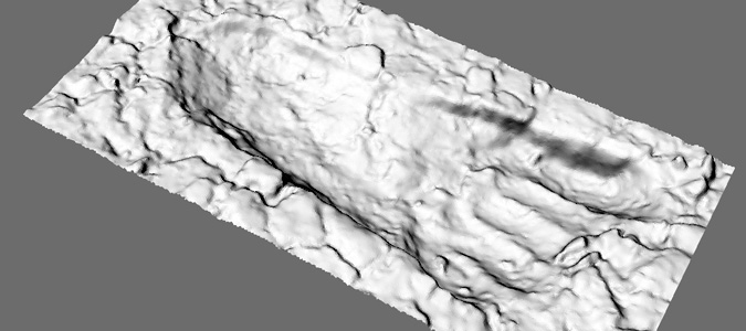
1. Clean up scan data
Electronic Scan files received from surveyor are are read into a 3D CAD application as a three dimensional mesh of triangles.
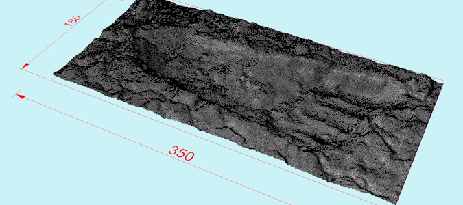
The model is manipulated in three dimensions to align it to a horizontal plane and fit into the required tile size. Any excess surface data is also trimmed of at this stage.
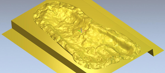
2. Create tool paths to make a pattern
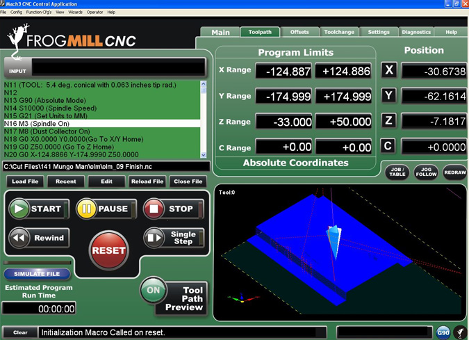
The model is then read into a CAM (Computer Aided Manufacturing) application which is used to produce the tool paths for the CNC (Computer Numerically Controlled) 3 Axis router.
In this application the raw material size is modelled and the 3D model of the footprint further manipulated to give a smooth finish towards the edges of the tile.
The tool to be used to cut the polystyrene material is selected. In this case a very fine tapered ball nose cutter is used to accurately replicate the fine detail in the footprint. The application then generates the required toolpath to cut the shape.
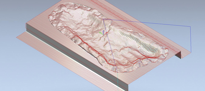
The CAM application generates positioning codes, called G & M codes, which are exported to a text file to suit the particular CNC machine.
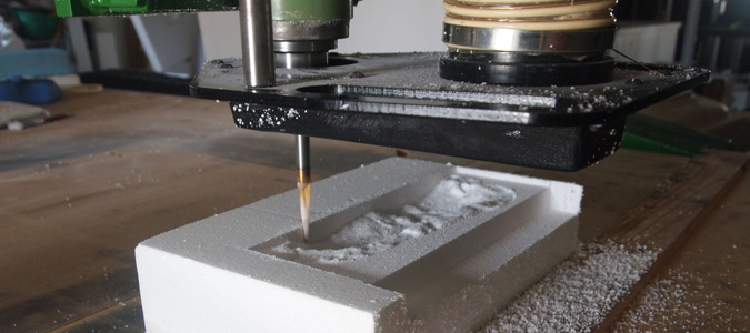
3. Cut the shape into the polystyrene
A block of polystyrene is cut to the required size and mounted into the CNC Router machine.
The file of G & M codes is loaded and the cutting process begins.
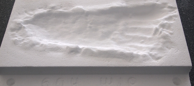
Once the machining process is completed the block of polystyrene is trimmed using a hot wire cutter to the required size and sharp edges blended by hand sanding.
4. Create a rubber mould from the polystyrene pattern
A sealer is applied to the polystyrene patterns and they are then boxed up in preparation to receiving the liquid rubber mould material.
The liquid rubber is mixed and poured over the pattern and allowed to cure for a few days to produce a flexible rubber mould.
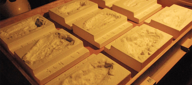
5. Create a Concrete Tile from the rubber moulds
These moulds are then filled with concrete to make the final tiles.
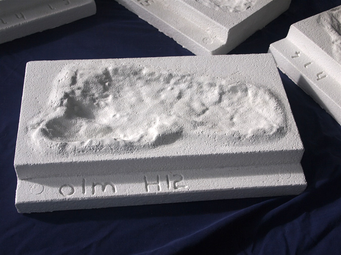
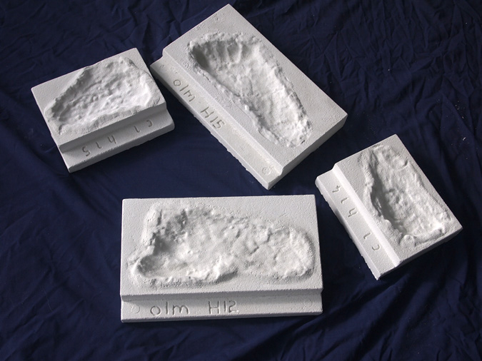
Final footprint tiles ready for installation.
Photographs, text, and footprint fabrication: John Balthazar, Industrial Carving Services